Electrode Materials and Design in Mag meters for Liquid Measurement
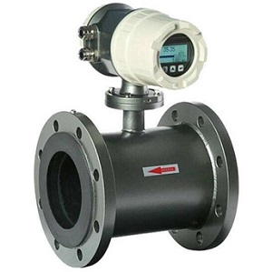
liquid magnetic flow meter design
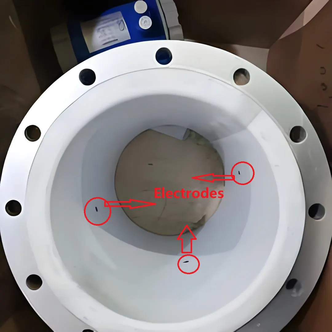
The electrode usually passes through the inner lining of the pipeline and comes into contact with the liquid. The electrode is usually a ball head bolt that passes through the inner lining material and is finally connected to the bolt by an electrical lead. Due to the contact between electrodes and liquids, electrode materials must be carefully selected. Some of the materials used are non-magnetic stainless steel (corrosive liquids), platinum iridium alloy, Monel, tantalum, titanium, zirconium (for corrosive liquids), and Hastelloy-C. Stainless steel is also recommended for use in measuring mud, as well as ceramic lining and electrode combinations.
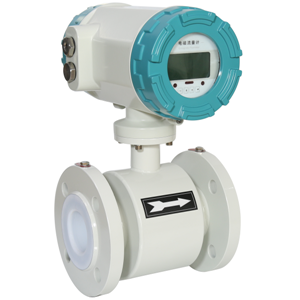
Electrodes for magnetic flow meter in paper pulp industry
In pulp and other applications, paper or other materials can collide with electrodes and cause noise. According to a manufacturer, covering the electrodes with porous ceramics may reduce this effect.
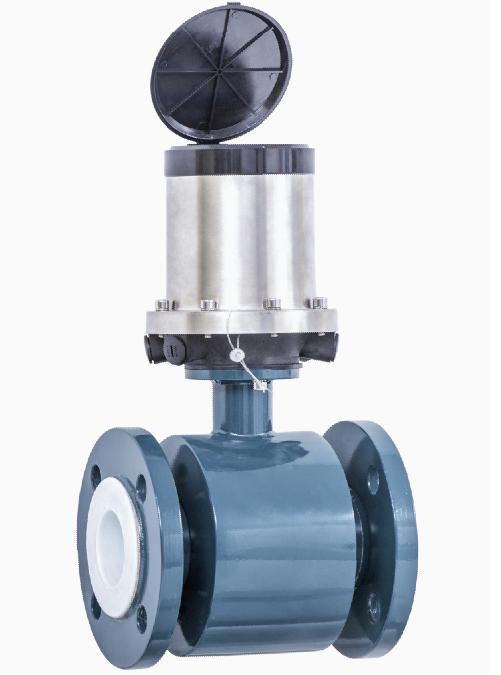
Slurry flow meters are needed.
Due to the contact between electrodes and liquids, various methods have been used to clean electrodes. Include:
• Wiping (a scraper or brush can pass through the center of the electrode to wipe the surface) (Rose and Vass, 1995);
• Melting (disconnecting other electronic connections and removing deposits on the electrode surface with a sufficiently large current);
• Ultrasonic cleaning (using ultrasonic waves to vibrate electrodes and cause local cavitation to achieve cleaning purposes);
• Mobile electrodes;
• Bullet like electrodes.
The method of selecting clean electrodes must be determined based on the characteristics of the sediment. In many cases, electrodes tend to self clean: when fluid passes through the electrode, sediment is restricted, and the conductivity of the coating on the internal surface of the instrument can be lower than that of most liquids. In modern DC systems, the input impedance can be large enough to ignore the influence of sediment. However, high impedance can cause thermal noise in the electrode signal. So, although high impedance means no systematic error, the repeatability of the instrument will decrease.
A magnetic field is typically generated by a set of coils and stacked magnetic yokes. It’s typical power consumption used to be 10~100 W, but now it can reach as low as 0.5 W. Since the use of long-life batteries, the lowest power consumption can be much lower than 0.5 W.
As a consequence of using AC excitation, a mutual inductance signal is generated due to the changing magnetic field in the loop formed by the combination of an electrode lead and a fluid. Figure 7 shows a poorly configured lead and the resulting region related to the changing magnetic flux. This area does not need to be very large to generate a signal comparable to the traffic signal. Its signal is orthogonal (with a phase difference of 90°from the flow signal), approximately Orthogonal voltage~2πfBA
Among them, f is the frequency, B is the magnetic induction intensity, and A is the area of the action loop projected in the direction of the magnetic field. For example, if f is 50 Hz, B is 0.02 T, and A is 1cm2, the orthogonal voltage is approximately 0.6 mV. However, the signal generated by moving at a speed of 5 m/s in a pipeline with a diameter of 0.1 m is 10 mV. The phase angle of the orthogonal voltage deviates by 90 °and is consumed as iron loss in the magnetic circuit, which cannot be reduced by mechanical design or electronic circuits. The use of DC excitation can solve this problem by directly measuring the flow signal when the magnetic field remains constant for a certain period of time. However, there are also other issues, which require a large voltage to quickly overcome the coil inductance and establish a magnetic field, and then maintain stability for flow measurement.
The installation of a component must not cause the pipeline to exceed pressure, and it must be ensured that the pipeline is filled with liquid. Usually, when installing the measuring pipe section, the electrode connection should be on a horizontal plane to avoid short circuiting of the electrode when bubbles appear at the upper part of the pipeline.
Most measuring tubes are made of stainless steel, allowing magnetic fields to pass through. The maximum pressure that the sensor can withstand is 1000 bar.
The design should also include options for use in harsh and hazardous environments.
Figure 6: Magnetic field coil and yoke

Figure 7: Relationship between magnetic field and signal leads
Transmitters of Mangetic flow meter (secondary component)
Transmitters of electromagnetic flow meters
Nowadays, many types of electromagnetic flow transmitters can achieve the required functions as
digital flow meter. The longest lasting type of communication used is 50 Hz or 60 Hz. This is because the main power supply is 50 Hz or 60 Hz, and at this frequency, the magnetic field and flow signals are also strong. But some common new designs use low-frequency square waves with different modes, which causes the orthogonal signal to attenuate before the flow signal is collected. The type of square wave excitation (DC excitation) mentioned here may have many different names depending on the manufacturer (Brobeil et al., 1993). The term 'DC type' should be used with caution, as early instruments had used DC type but were unsuccessful. In DC design, the magnetic field strength is relatively small, but the electronic noise and electromechanical effects in the mud are the same as in AC design. Therefore, the latest designed DC instrument will have a special high-power power module to solve this problem.
Bonfig et al. (1975) described one of the first successful DC designs, called a key DC field. Hafner (1985) described another system called switched DC, which has functions such as noise reduction (active and passive shielding), electrochemical activity, amplifier periodic zeroing, multiple signal sampling, higher acquisition frequency (up to 123 Hz), digital filtering, and the use of flow noise analysis circuits. The use of low energy consumption in the design (reduced to 1.5W, with reduced size and weight) meets the requirements of inherent safety and battery drive. The microprocessor control also provides self detection, temperature compensation, interchangeable primary and secondary tools, and interactive functions. In addition, the electrode also provides grounding and air tube inspection functions. Herzog et al. (1993) studied switched DC designs with an electronic reference point in one cycle and discussed the use of a third electrode in partially full pipelines.

Figure 8: AC SystemConversion Circuit Diagram
The output signal is usually 0~10mA or 4~20mA. It can provide two to three range adjustment knobs to meet the full range reading of fluids at flow rates of 1~10m/s. But now, they have been replaced by microprocessor technology. By using smart/intelligent instruments to automatically adjust the output signal range, it has digital transmission function and larger range.
Figure 8 shows a typical block diagram of an AC circuit. The demodulator eliminates the orthogonal voltage through the reference signal, and the AC circuit obtains the ratio of the flow signal to the reference signal.
The block diagram in Figure 9 (a) is a typical method adopted in DC systems. As shown in Figure 9 (b), the sampling at time τn, τn+1, and τn+2 amplifies the baseline drift of the square wave signal caused by electrochemical and other effects, so it is clearly reasonable to use three sampling points.
Zero drift may appear in some instruments, but it is usually weak. It may be caused by the inability to completely suppress unexpected voltages, especially orthogonal voltages. Although the cut-off method is adopted at low flow rates, the DC system claims to solve the zero drift problem at this time, but this is difficult to confirm. Low traffic cutoff is usually limited to 1% of the upper limit range (Ginesi and Annarummo, 1994) or possibly lower.
The overall uncertainty of the converter is 0.2% for a wide range of main voltages, orthogonal signals, temperature fluctuations, etc.It can also measure micro flow signals with low precision.

Figure 9: Schematic diagram of transmitter circuit for DC system
(a) Route; (b) Measurement signal
Commercial magnetic flow meter converters will provide:
- The instruction response time is 0.1 s;
- Range ratio: maximum 1000:1;
- Flow range: 0.005~113000 m³/h interval;
- Unit pulse overcurrent volume: 0.01~10L/pulse.
The characteristics provided by the manufacturer include:
- Two phase cables with inherent safety are used for power supply and signal transmission of sensors;
- Realize digital signal transmission by modulating analog signals through communication;
- Protection between components, IP65 protection for converters;
- Dual frequency (see Figure 10) is beneficial for both high and low frequencies: processing signals separately before frequency merging will result in low flow stability and low noise;

Figure 10: Schematic diagram of dual frequency working circuit
(authorized reference by Yokogawa Europe B. V.)
- Interference free transmission;
- Self check or increase detection data;
- Air traffic detector, using electrodes to sense the status of air traffic and sound an alarm (Ginesi and Annarummo, 1994);
- Grounding electrode;
- Main electrode contamination detection;
- Measure bidirectional fluid using appropriate circuits;
- Automatic range adjustment.
Application specific integrated circuits (ASICs) can provide functions such as automatic inspection systems to detect fluid reverse flow and other faults, alarms, dual range, and some interface communication (Vass, 1996).
Magnetic flow meter Calibration and operation
SHD series Electromagnetic flow meter calibration workshop
Due to the differences between instruments during the flow meter manufacturing process, electromagnetic flow meters need to be calibrated, which is usually done by the flow meter manufacturer. For example, a magnetic flow meter manufacturer provides a standard instrument with 13 calibration points, which is commonly referred to as wet calibration. Dry calibration refers to the calibration of electromagnetic flow meters by measuring magnetic fields to derive fluid signals. The relationship between the magnetic field at a specific point and all ranges of the instrument is not as straightforward as equation (12.2), which means that any current dry calibration should be treated with caution.
The operation of the electromagnetic flow meter should not be affected by the conductivity of the fluid, so the conductivity of the fluid should be the same throughout the entire area of the flowmeter. Assuming that the conductivity is large enough to make the output impedance of the primary component at least two orders of magnitude smaller than the input impedance of the secondary component. Moreover, significant changes in conductivity can cause zero point errors in AC electromagnetic flow meters. Although some people believe that the DC pulse type is not affected by changes in conductivity above a certain threshold (Ginesi and Annarummo, 1994), one manufacturer still holds the opposite view, believing that AC type should be used for measuring bidirectional flow, mud, low conductivity fluids, and non-uniform flows with rapidly changing conductivity. Anyway, the continuous development of DC type will ensure that it is equally suitable for the above situations.
The output impedance of a component can be approximately expressed as
R≈1/dσ(Ω)
Where d is the diameter of the electrode and σ is the conductivity.
The typical impedance of an instrument with an electrode diameter of 0.01m can be obtained from equation (3), as shown in Table 2.
|
Table2
Output resistance of instrument measuring tube
with electrode diameter of 0.01m
|
|
Liquid conductivity
|
Resistance
|
|
S/m
|
μS/ cm
|
Ω
|
|
The best electrolyte
|
About 10²
|
About 10⁶
|
1
|
|
Seawater
|
About 4
|
About 4×10⁴
|
25
|
|
Tap-water
|
About 10⁻²
|
About 10²
|
10000
|
|
Pure water
|
4×10⁻⁶
|
4×10⁻²
|
25 000 000
|
A typical secondary component with an input impedance of 20 × 10⁶/Ω can match the conductivity of the first three fluids in Table 2, but cannot match the last one. Manufacturers will limit the minimum value of conductivity for specific size instruments. For example, for electrodes with a diameter of 25~100mm, it is acceptable to have a conductivity as low as 20 μS/cm, but at least one manufacturer can provide a conductivity reduction of 0.05 μS/cm.
Due to the disruption of electrical continuity and conductivity uniformity, as well as the uncertainty of the measured object, the presence of gas in the fluid will cause errors. Flow meters should operate under conditions where these factors can be ignored.

Magnetic flow meter is measuring seawater flow rate
Where is the electromagnetic flow meter used?
Electromagnetic flow meters are widely used in liquid flow measurement. It is highly suitable for any conductive liquid and is almost always successful in its applications. An industrial expert once said that the only problem he encountered was measuring crystallized powdered sugar, and the reason for the failure may be fluid issues or incompatibility. If it is applied to measure two-phase or multiphase flow, where continuous components must be conductive, the signal is generated by the velocity of that component. If it is applied to liquid metals, its physical principles will become more complex.

Magmeter is highly suitable for any conductive liquid
The applications of electromagnetic flow meters include viscous fluids, corrosive chemicals, abrasive slurries, and operating fluids with startup and shutdown capabilities, but the flow tube should be full (some manufacturers provide models that can measure non full tube flow), and the electrodes should not be short circuited by bubbles (Ginesi and Annarummo, 1994). If possible, the measuring pipeline should be flowing upwards at this time. If it is a horizontal pipeline, the electrode should be in the horizontal diameter direction. If the instrument is installed at a lower position in the pipeline, it must be monitored for the possibility of mud or other fluids adhering to the electrodes. Attachments have conductivity different from fluid properties and can form a partially conductive layer to change the internal diameter and length of the instrument. If the speed of the instrument is maintained above 2~3m/s, the probability of sedimentation will decrease. Cone shaped electrodes can also reduce sedimentation and electrode cleaning systems can be used. Non Newtonian fluids may alter the response. Wear resistant mud may cause lining wear near bends in pipelines, and pipeline protection can reduce wear. The fluid used for cleaning must be compatible with the working fluid. Additives can also cause uneven conductivity.
 Magnetic flow meter is measuring corrosive liquid
The communication incentive technology was once more suitable for measuring the application of mud carrying a large amount of gas. This slurry is uneven, with a large amount of irregularly sized solid particles or a tendency to form mud lumps, accompanied by pulsating flow. About 15% of industrial flows have this situation, including pulp and mortar. In these applications, DC pulse technology has gradually become an important choice to replace AC technology.
In the new flowmeter, radio frequency interference (RFI) effects will be eliminated. According to the manufacturer's instructions, signal cables must be shielded and grounded. Rose and Vass (1995) discussed the application of electromagnetic flowmeter technology in more difficult industrial processes:
Chemical:
· acid,
alkali,
polymer, lotion and rubber solution
Pharmaceutical:
· spray coating, seasoning, medical and health products
Mining and mineral:
· iron ore slurry, pyrite, magnetite, pyrite, copper, alumina
Food and beverages:
· beer, soda, toothpaste, milk, ice cream, sugar,
juice
Water and waste:
· water,
wastewater, sewage, sludge, digestive fluids

Wastewater flow measured by magmeter
Pulp and paper:
· black and white liquids, brown raw materials, bleaching chemicals, additives
Nuclear fuel processing plant:
·radioactive and non-radioactive fluids (Finlayson, 1992)
Recent literature reports on applications include:
·Can be used to deal with problems in liquid lead bismuth flow (Kondo and Takahashi, 2005);
·Monitor the performance of the pump (Anon, 2002);
·Measurement of slurry flow using capacitive electrodes (Okada et al., 2003);
·Monitoring wastewater (Kwietniewski and Mizstka Kruk, 2005);
·Continuous garbage disposal: refining pipes, blowing pipes, and recycling pipes (Okada and Nishimura, 2000);
·Drilling flow (Arnold and Molz, 2000);
·Precision measurement of alkylate and sulfuric acid production (Dunn et al., 2003).
For this list, slag, cement, slurry (abrasive), furnace charge reagents, and special applications such as ultra-low speed, transactional transportation, liquids with steam tracing, blast furnace fluids, batching, and corrosive liquids may also need to be added.
Under high-frequency measurement conditions (120 measurements per second), AC flow meters can measure the pulse flow rate of pumps.
Some manufacturers provide electromagnetic flow meters with dimensions of 2~25mm for measuring milk. Manufacturers also provide their own specific size instruments for use in hygiene and daily chemical products, which can be used in high-speed mass production processes with a repeatability rate of up to 0.2%.
What are the advantages of using electromagnetic flow meters?
1. Theory suggests that the response of electromagnetic flow meters is linear (except for the influence of different flow velocity distributions), and the only reason why the instrument cannot display zero flow is zero drift. This is one of the few instruments that can achieve such a function, but it has also been unfairly judged because zero drift can still be observed. Modern designs often use low flow range truncation to avoid this issue.
2. Unstoppable flow is the most valuable, especially when the fluid contains solids or when passing through obstacles can damage the flow channel.
 Magnetic flow meter Full bore design
 ensure unstoppable flow
3. There are no movable parts.
4. The sensitivity of upstream pipe components is comparable to other flow meters, only weaker than volumetric flow meters,
Coriolis flow meters, or
ultrasonic flow meters with two or more sound beams.
What are the disadvantages of using electromagnetic flow meters.
Its main drawback is that it is limited to measuring conductive liquids. Although the laboratory has designs for non-conductive liquids (transformer oil or diesel), only one or two commercial designs have attempted in this regard.
For a period of time, some people believed that sensitivity to upstream disturbances was a weakness, but this could be one of its strengths. Compared with electromagnetic flow meters, only a few flow meters are less affected by upstream flow velocity distribution during operation. Another frequently mentioned disadvantage is zero drift, as early designs were found to produce significant errors at extremely low flow rates. Once again, it should be noted that no flow meter can be used outside the range or at flow rates lower than possible. In fact, at least one commercial electromagnetic flowmeter claims a range ratio of 1000:1.


 Low flow magnetic flow meter
2025/07/28
Low flow mag meters can handle liquid flowas low as to 0.33 LPM (0.09GPM), the mini mag flow sensor size we can provideis 1/8”,1/4”,3/8”,1/2”,3/4”. Micro flow magnetic flow meters are used widely...
VIEW
Low flow magnetic flow meter
2025/07/28
Low flow mag meters can handle liquid flowas low as to 0.33 LPM (0.09GPM), the mini mag flow sensor size we can provideis 1/8”,1/4”,3/8”,1/2”,3/4”. Micro flow magnetic flow meters are used widely...
VIEW
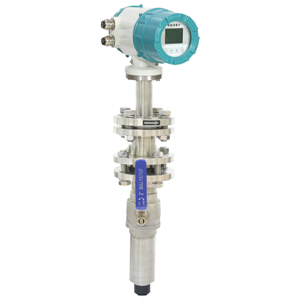 Insertion type electromagnetic flow meter
2025/07/28
Insertion probe electromagnetic flow meter is suitable for pipeline size over 8 inches; it is ideal solution for large pipe size conductive liquid flow measurement ,such as waste water, portable water...
VIEW
Insertion type electromagnetic flow meter
2025/07/28
Insertion probe electromagnetic flow meter is suitable for pipeline size over 8 inches; it is ideal solution for large pipe size conductive liquid flow measurement ,such as waste water, portable water...
VIEW
 Sanitary Magnetic flow meter
2025/07/28
SHD-SE13 Magmeter sensor is a type sanitary type flow measuring device.It can measure tap water, tomato paste, liquid egg, molasses, juice, vinegar and so on which are widely used in food-processing,...
VIEW
Sanitary Magnetic flow meter
2025/07/28
SHD-SE13 Magmeter sensor is a type sanitary type flow measuring device.It can measure tap water, tomato paste, liquid egg, molasses, juice, vinegar and so on which are widely used in food-processing,...
VIEW
 Slurry Magnetic Flow Meter
2025/07/28
SHD-SE16 Series Slurry Magnetic Flow Meter is for flow measurement in high-noise slurry applications; flow sensors for sludge, slurries and solids.
VIEW
Slurry Magnetic Flow Meter
2025/07/28
SHD-SE16 Series Slurry Magnetic Flow Meter is for flow measurement in high-noise slurry applications; flow sensors for sludge, slurries and solids.
VIEW
 SHD Series Battery Powered Electromagnetic Flow Meter FAQ
2025/07/28
Question 1 The battery-powered SHD Series Magnetic flow meter can also have external 12V or 24V DC power supply?Answer:Yes, we can this kind of mag meter with both battery powered and 12V power supply...
VIEW
SHD Series Battery Powered Electromagnetic Flow Meter FAQ
2025/07/28
Question 1 The battery-powered SHD Series Magnetic flow meter can also have external 12V or 24V DC power supply?Answer:Yes, we can this kind of mag meter with both battery powered and 12V power supply...
VIEW
 Electromagnetic Flowmeter
2025/07/28
Buy Quality Electromagnetic Flow meter from China manufacture in low price and fast delivery time. Get the Mag meter Price cost now from SILVER AUTOMATION INSTRUMENTS.
VIEW
Electromagnetic Flowmeter
2025/07/28
Buy Quality Electromagnetic Flow meter from China manufacture in low price and fast delivery time. Get the Mag meter Price cost now from SILVER AUTOMATION INSTRUMENTS.
VIEW


 Email
Email
 WA
WA
 Inquiry


