Straight Pipe Length Requirements
To ensure stable and accurate flow measurement, proper straight pipe lengths must be maintained upstream and downstream of the
vortex flow meter.
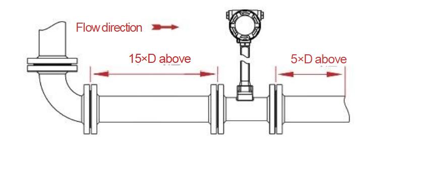
(1) Reducing Pipe (Flow Contraction)
For reducing pipes, provide at least 15D of straight pipe upstream and 5D downstream of the flow meter.
(D = Nominal inner diameter of the vortex flow meter)
(2) Expanding Pipe (Flow Expansion)
In cases of pipe expansion, maintain the same straight lengths: 15D upstream and 5D downstream.
(3) Elbows and Bends
For each elbow or pipe bend, install 15D of straight pipe upstream and 5D downstream to stabilize the flow before measurement.
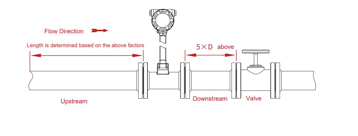
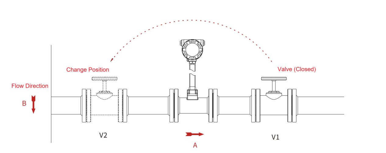
(4) Valve Position
Ideally, the valve should be installed downstream of the flowmeter.
If it must be installed upstream, extend the upstream straight length to at least 25D and keep 5D downstream. This helps minimize flow disturbance caused by valve operation.
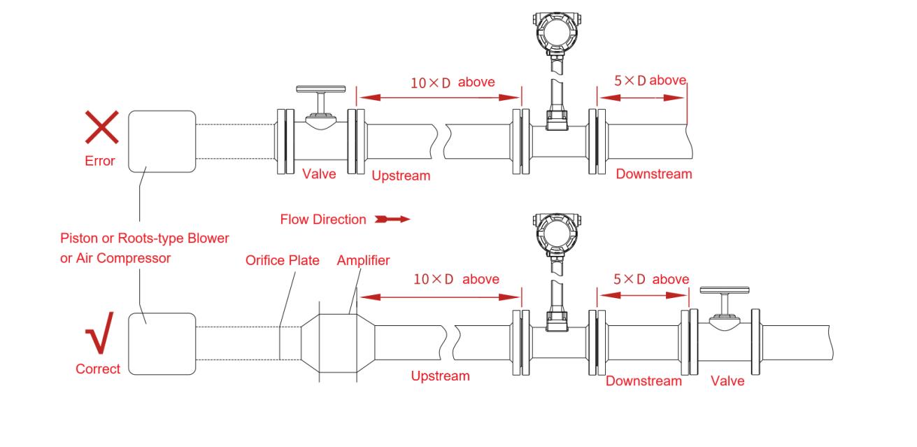
(5) Piston or Plunger Pumps
When using piston or plunger pumps, install an accumulator upstream of the flowmeter to reduce pulsating flow and ensure stable readings.
(6) Pulsating Flow in Gas or Liquid Lines
Gas pipelines with piston or Roots-type blowers, or high-pressure liquid lines with plunger pumps, often generate pulsations. To mitigate this, install a pulsation dampener (such as an orifice plate or expansion chamber) upstream of the meter.
(7) T-Type Pipe and Valve Location
For T-type pipelines, placing the valve upstream of the flowmeter can prevent pulsation pressure from affecting zero-point stability. Relocate the valve to avoid signal fluctuations during flow interruptions.
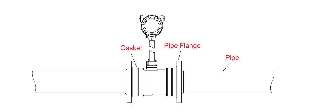
(8) Gaskets
Ensure gaskets do not protrude into the pipeline, as this may cause turbulence and measurement inaccuracies.
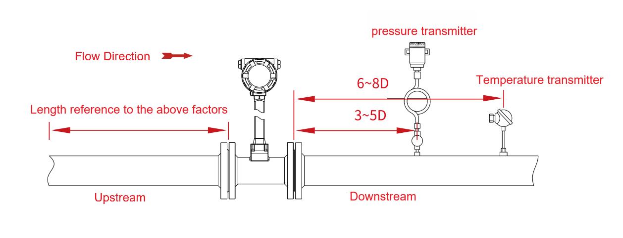
(9) Pressure and Temperature Tapping Points
Pressure tapping point: 3–5D downstream of the flowmeter
Temperature tapping point: 6–8D downstream of the flowmeter
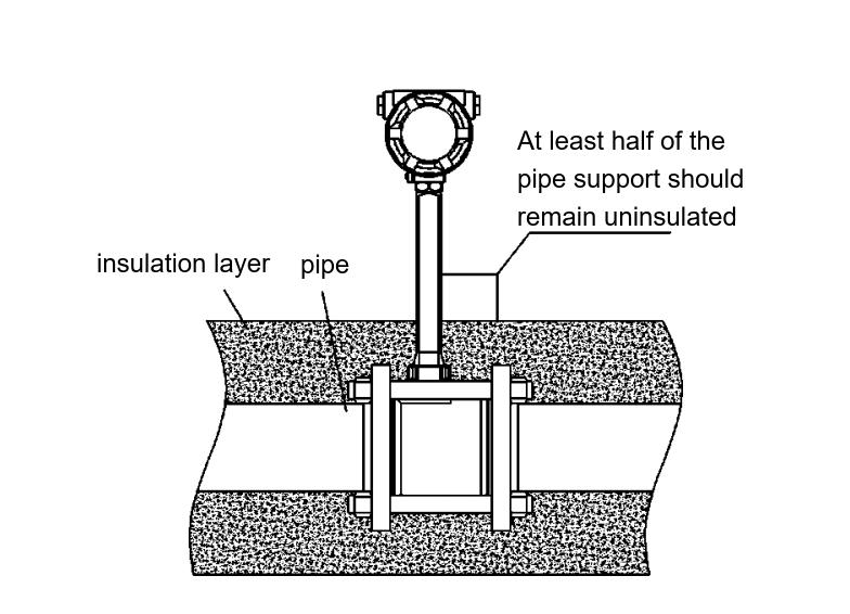
(10) Thermal Insulation
When insulating pipelines carrying high-temperature fluids, do not cover the transmitter bracket of the flowmeter to allow proper ventilation and maintenance access.
(11) Pipeline Cleaning
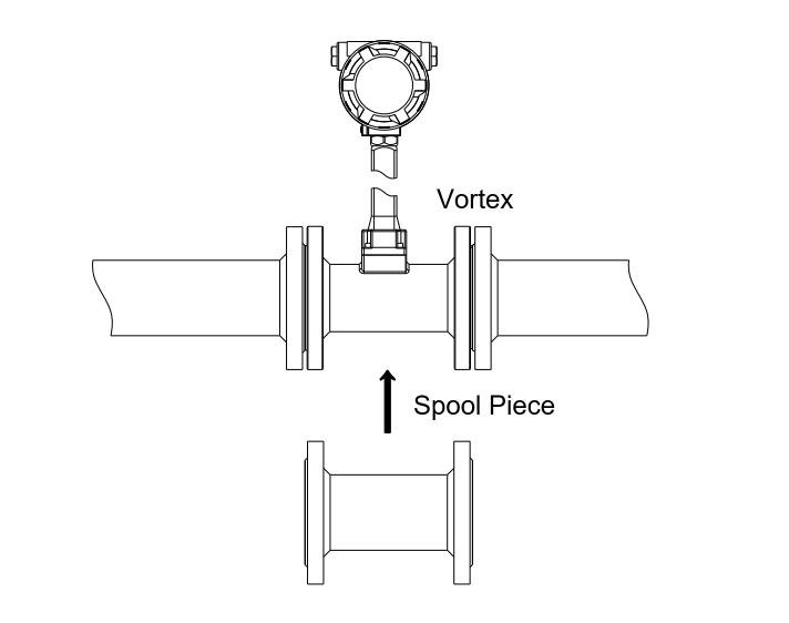
Before commissioning, flush newly installed or repaired pipelines to remove rust, welding slag, or debris. Use a bypass line for flushing to avoid damaging the meter. If no bypass exists, temporarily replace the meter with a spool piece during cleaning.
Installation Location Requirements
Vortex flowmeters can be mounted indoors or outdoors, provided that vibration is minimized. If vibration is significant, add pipe supports to reduce mechanical stress. The connecting pipeline’s internal diameter should be 1–5 mm larger than that of the flowmeter to prevent flow restriction.
1. Gas and
Steam Applications
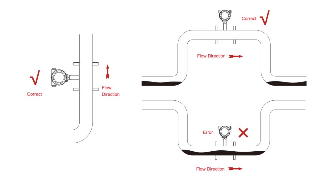
Install vertically to avoid condensate accumulation.
For horizontal installations, place the meter at the highest point of an inverted U-shaped section.
Avoid installing at the lowest point of a U-shaped pipe, where condensate may collect and cause false readings or potential damage.
2. Liquid Measurement Applications
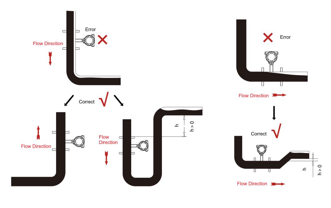
Ensure the meter tube remains completely full of liquid.
The flow direction should be upward whenever possible.
If downward installation is necessary, position the meter below the downstream pipeline to maintain a full flow condition.
Avoid installing the flowmeter at the highest point of a pipeline, as gas bubbles may form and reduce accuracy.
To prevent cavitation or bubble formation caused by valve-induced pressure drops, install the flowmeter upstream of control valves.
3. Mixed-Phase Flow
For accurate readings, the measured medium must be single-phase (gas, steam, or liquid). In two-phase or mixed-phase conditions, the measurement accuracy will degrade significantly.
Installation Procedures and Precautions
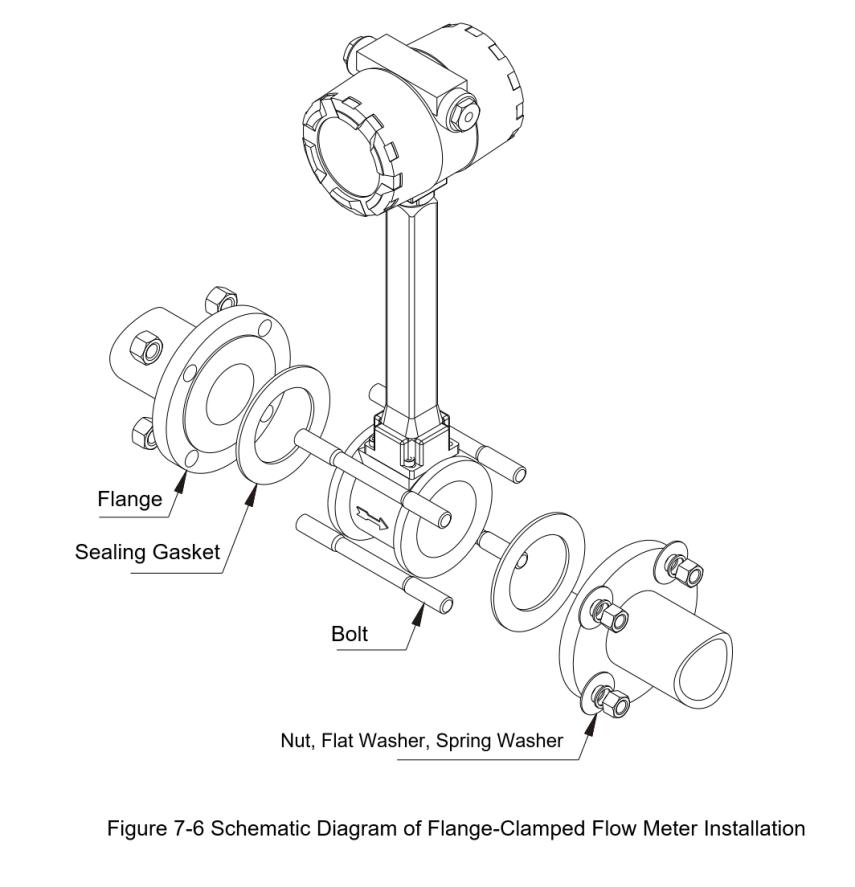
1. Flange-Connected and Flange-Clamped Flowmeters
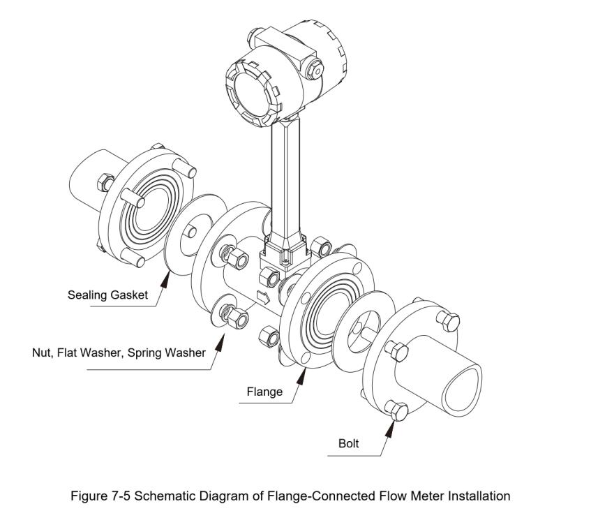
Ensure pipe alignment and coaxiality between the flowmeter and the pipeline before installation.
For new pipelines, always flush out debris and welding residue to prevent obstruction or inaccurate readings.
By following these installation practices, vortex flowmeters can achieve optimal performance, ensuring long-term stability, accuracy, and durability in industrial applications involving gas, steam, or liquid flow measurement.
