Table of Contents
What is turbine flow meter and TUF history
Turbine flow meters wide applications around the world
Update flow technology of turbine flow meter all the time
Working Principle of turbine flow meter
What is the formula for calculating turbine?
How do you calculate turbine flow meter factor /coefficient?
Advantages and disadvantages of turbine flow meter
Turbine flow meter types
Turbine flow sensor structure
Accuracy of turbine flow meter
Selection of flow range of turbine flow meter
Flow meter accuracy level for different applications
What fluids can be measured by turbine flow meter?
Turbine flow meter requirements for liquid viscosity
Requirements for gas density for gas turbine flow meter
Conversion of volume flow to mass flow
Application which turbine flow meter is not suitable
Cost when you select turbine flow meter
Steps to choose turbine flow meter
Installation Precautions
Standards and verification procedures
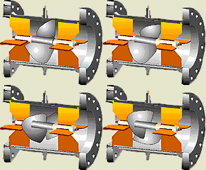
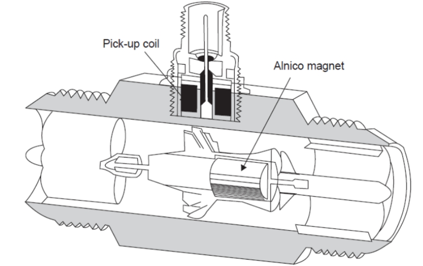
Turbine flow meter construction
|
1-Fastener; |
Turbine flow meter characteristic curve
The turbine flow sensor factor is verified by the flow calibration device. It completely ignores the flow mechanism of the fluid inside the sensor. It treats the sensor as a black box and determines its conversion coefficient based on the input (flow rate) and output (frequency pulse signal). It is convenient practical application. However, it should be noted that this conversion coefficient (instrument coefficient) is conditional, and its calibration conditions are reference conditions. If it deviates from this conditional coefficient during use, the coefficient will change. The change depends on the turbine flow sensor type, pipeline installation conditions and fluid physical parameters.
Scholars at China and abroad have proposed many theoretical flow equations, which are applicable to various turbine flow sensor structures and fluid working conditions. To date, the hydrodynamic characteristics of turbine flow meter characteristics are still not very clear, and they have a complex relationship with fluid physical properties and flow characteristics. For example, when the flow field has vortices and asymmetric velocity distribution, the hydrodynamic characteristics are very complex. The Turbine flow meter facotr cannot be derived by theoretical formula, and the turbine flow transmitter coefficient still needs to be determined by actual flow verification. However, the theoretical flow equation has great practical significance. It can be used to guide the design of sensor structure parameters and the prediction and estimation of the law of instrument coefficient changes when the field use conditions change.
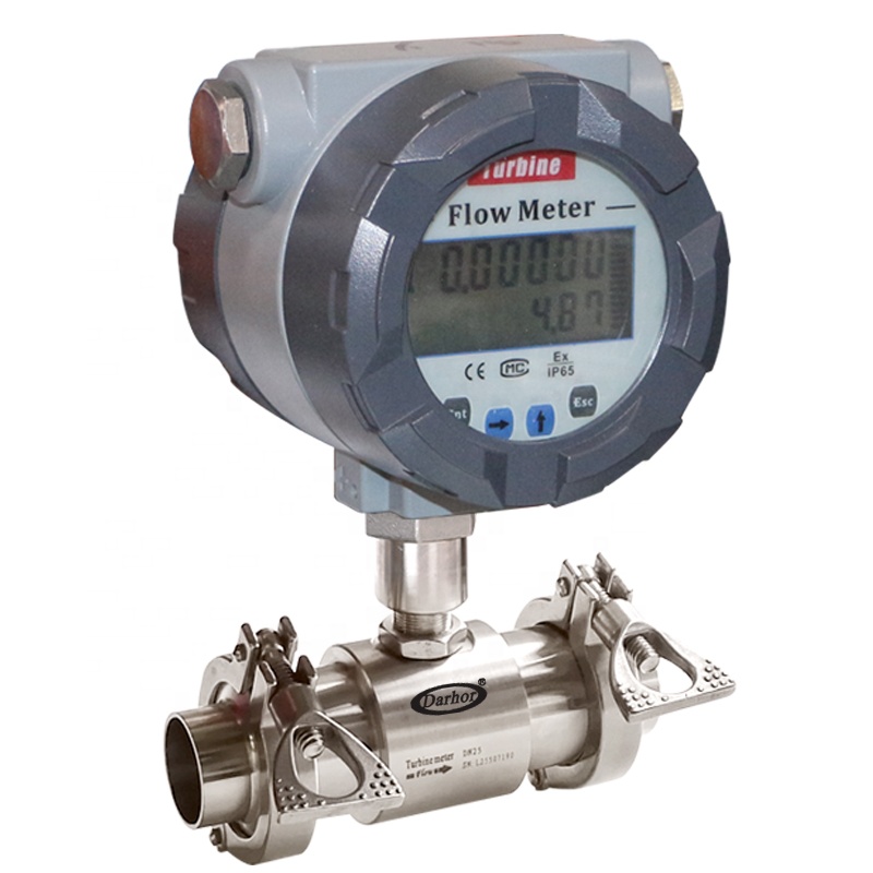
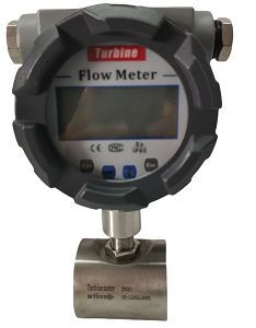
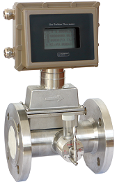
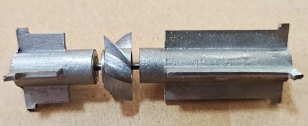
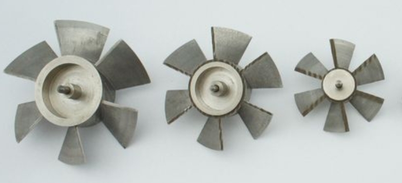
Generally speaking, turbine flow meter is chosen mainly for its high accuracy still at low price cost. At present, the accuracy of TUF turbine flow meter is roughly as follows: for liquids measurement turbine flow meter, the international market is ±0.5%R and ±1%R, for gas flow measurement devcie, is ±1%R and ±1.5%R. The above accuracy refers to the range of 6:1 or 10:1. Typical parameters of turbine flow sensors from Silver Automation Instruments are shown in below table. In addition to being related to the quality of the product itself, accuracy is also closely related to the conditions of use.
If the range is narrowed, the accuracy can be improved; especially for standard flow meters used as standard flow standard devices, if used at fixed points, the accuracy can be greatly improved.
The higher the accuracy of the flow meter, the more sensitive it is to changes in the on-site conditions. In order to maintain its high accuracy, special processing of the instrument coefficient is required. One processing method is the so-called instrument coefficient floating processing method. That is, the following on-site conditions are processed in real time: a) viscosity is affected by temperature; b) density is affected by pressure and temperature; c) sensor signal redundancy (a sensor outputs two signals, and their ratio is monitored); d) long-term stability of the coefficient (determined by a control chart), etc.
For trade storage and transportation handover measurement, online verification devices are often equipped to facilitate regular verification.
The instrument accuracy listed in the turbine flow meter manufacturer's instruction manual is the basic error. The additional error should be estimated on site, and the on-site error should be the combination of the two.
The selection of the flow range of turbine flow meter has a great influence on its accuracy and service life. Generally, the speed corresponding to the maximum flow during operation should not be too high. The use conditions are divided into continuous flow measurement operation and intermittent flow measurement operation. Continuous operation means that the working time exceeds 8 hours per day, and intermittent operation means that the working time is less than 8 hours per day. For continuous operation, the maximum flow should be selected at the lower limit of the flow instrument's upper limit flow, while for intermittent operation; turbine flow sensor can be selected at the higher limit. Generally, for continuous flow measurement, the actual maximum flow is multiplied by 1.4 as the upper limit flow of the flow range, while for intermittent operation, it is multiplied by 1.3.
If the diameter of the turbine flow sensor is inconsistent with the diameter of the process pipeline, the pipeline should be modified with a reducer and an equal-diameter straight pipe.
For process pipelines with low flow rates, the minimum flow rate becomes the first issue to be considered when selecting the turbine flow sensor size. Usually, the actual minimum flow rate multiplied by 0.8 is used as the lower limit flow rate of the flow range, leaving a certain margin. If the turbine flow transmitter is equipped with a segmented linearization function, when the sensor flow lower limit value cannot meet the actual minimum flow rate, the turbine flow meter manufacturer should be required to perform flow calibration at the actual minimum flow rate and its vicinity, and input the measured instrument coefficient into the turbine flow transmitter, so that the flow lower limit value of the instrument can be reduced while maintaining the measurement accuracy.
The requirements for the accuracy level of the instrument should be cautious and should be considered from an economic perspective. For example, the trade settlement instrument for large-diameter oil (gas) pipelines is of great economic significance, and it is cost-effective to invest more in the instrument. As for the small transmission volume or process control, only a medium level of accuracy is required, and high accuracy should not be blindly pursued. The intrinsically safe explosion-proof sensor is compatible with the safety barrier model and manufacturer, and the explosion-proof level and approval number are checked. If you want to display mass flow (or volume flow under standard conditions), you need to select a pressure, temperature sensor or density meter or choose mass flow meter directly. The turbine flow meter display instrument is now included in the flow computer based on a microprocessor that can communicate with the host computer. The instrument is far superior to the old turbine flow display in terms of instrument functions and applicable scope. At present, all types of flow meters used as trade measurement tend to be equipped with direct reading display devices. Not only is there a display of total measurement, but a compensator (a fully functional flow computer) can also be added to output remote transmission signals.
Turbine flow meter requires that the fluid must be clean (or basically clean), single-phase and low-viscosity. Examples of commonly used fluids are as follows: including turbine flow meter for water, diesel, air, oxygen, high-pressure hydrogen, milk, coffee, etc.; petrochemicals: gasoline, light oil, jet fuel, light diesel, naphtha, ethylene, polyethylene, styrene, liquefied gas, carbon dioxide and natural gas; chemical solutions: amethanol, , etc.; organic liquids: alcohol, ether, benzene, toluene, xylene, butadiene, carbon tetrachloride, methylamine, acrylonitrile, etc.; inorganic liquids: formaldehyde, acetic acid, etc. For corrosive media, attention should be paid to the selection of materials used. It is not recommended to use media with many impurities or abrasive media.
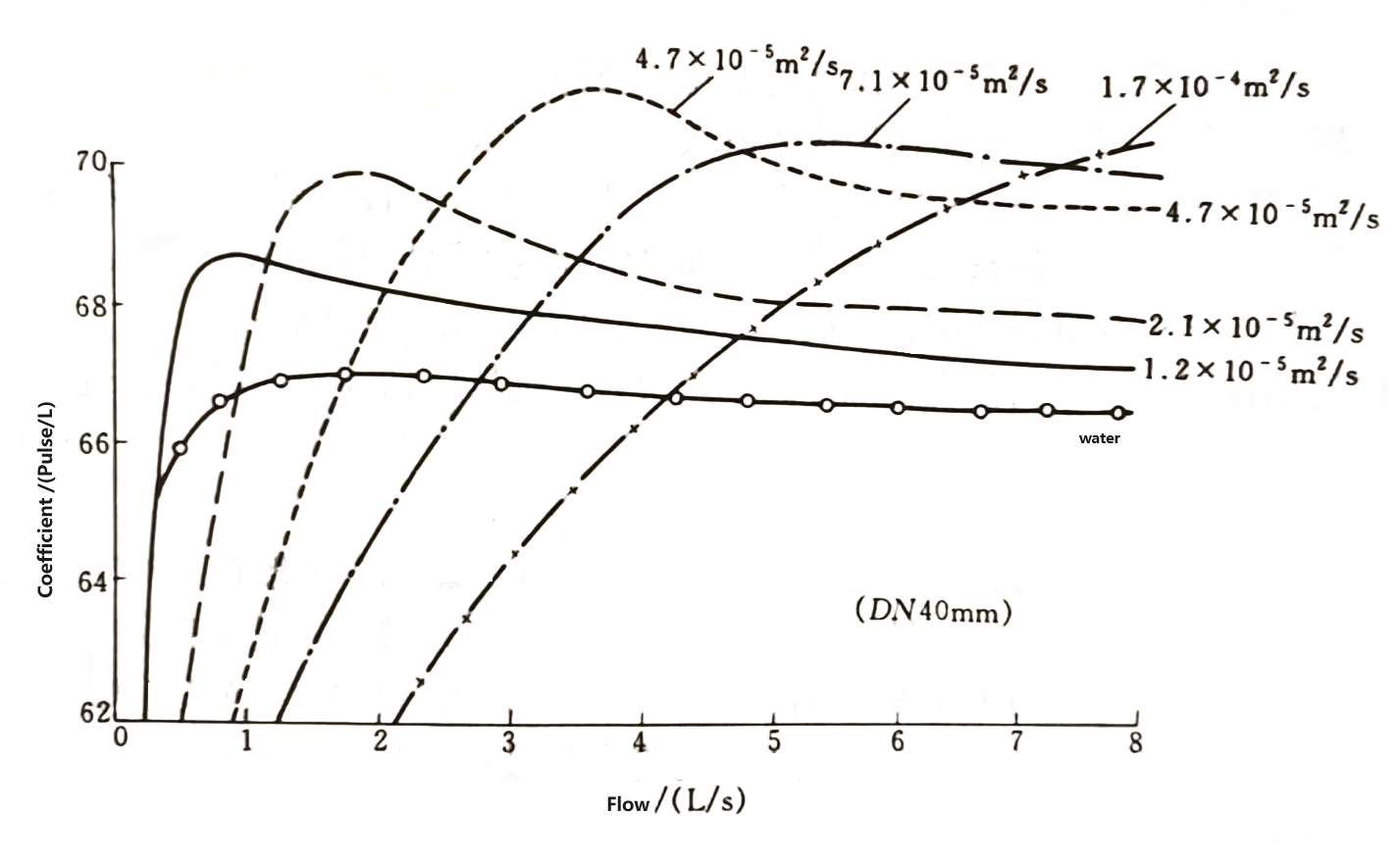
Liquid turbine flow meter is a viscosity-sensitive flowmeter. Below Figures show the relationship between the viscosity and the instrument coefficient of the straight blade and spiral blade TUF liquids, respectively. It can be seen from the figure that when the fluid viscosity increases, the linear region of the instrument coefficient becomes narrower and the lower limit flow rate becomes smaller.
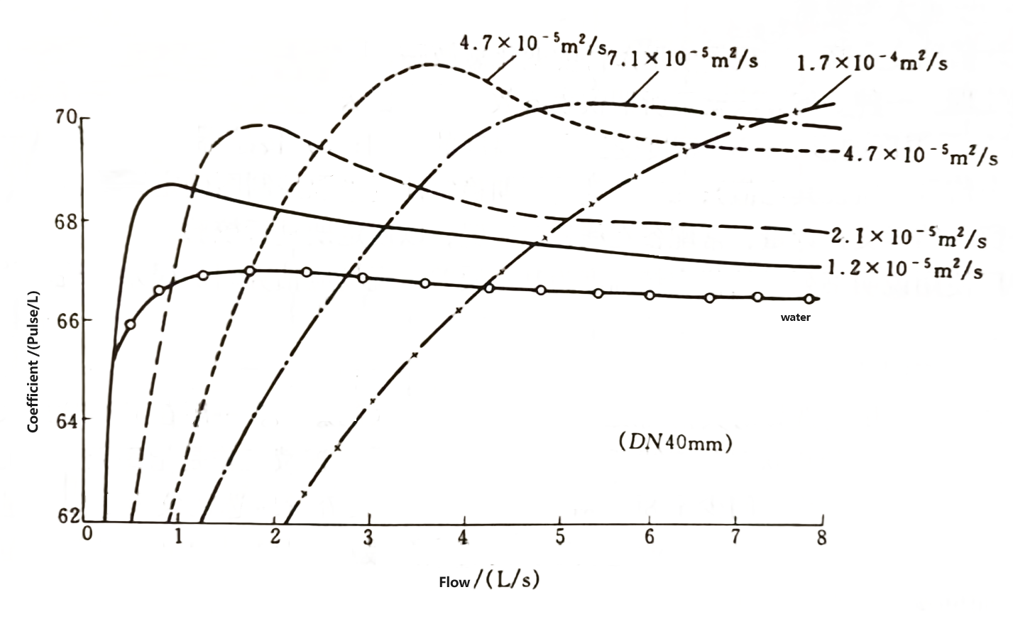
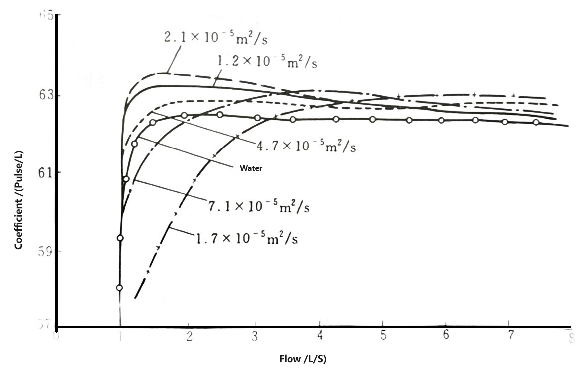
For liquids, water is usually used to calibrate the turbine flow sensor. When the accuracy is 0.5, it can be used for liquids below 5×10⁻⁶mm²/s without considering the effect of viscosity. When the fluid viscosity is higher than 5×10⁻⁶mm²/s, it can be calibrated with a fluid of equivalent viscosity without making viscosity corrections. In addition, some measures can be taken to compensate for the effect of viscosity, such as narrowing the range of use, increasing the flow rate lower limit, or multiplying the instrument coefficient by the Reynolds number correction coefficient, etc.
The influence of viscosity on the instrument coefficient is related to the sensor structure type and parameters, aperture size, etc. There are several ways to express the effect of viscosity on the instrument coefficient: the relationship between the instrument coefficient and the Reynolds number, the relationship between the instrument coefficient and the output frequency at several viscosities and the relationship between the instrument coefficient and the ratio of the output frequency divided by the kinematic viscosity And so on. Some turbine flow meter manufacturers have this information, but not all manufacturers have it.
In the application of petroleum industry, TUF has been promoted and used because of some characteristics compared with volumetric flowmeter.
The main features are light weight, simple and compact structure, large flow capacity, easy maintenance, tolerance of some impurities without blocking the flow channel, and superior safety. As early as the 1960s, the North Sea Oilfield in the United Kingdom used TUF for crude oil measurement, and Japan's Tokiko also launched a wide viscosity Porter type TUF for heavy oil measurement.
Gas turbine flow meter mainly considers the influence of fluid density on instrument factor. The influence of density is mainly in the low flow area, as shown in below Figure. The increase of density (i.e. pressure increase) makes the straight line part of the characteristic curve expand to the lower limit flow area, the range of the sensor is expanded, and the linearity is improved. If the gas turbine flow meter is calibrated in air at normal pressure, the working pressure of the measured medium is different during use, and its lower limit flow is calculated by the following formula

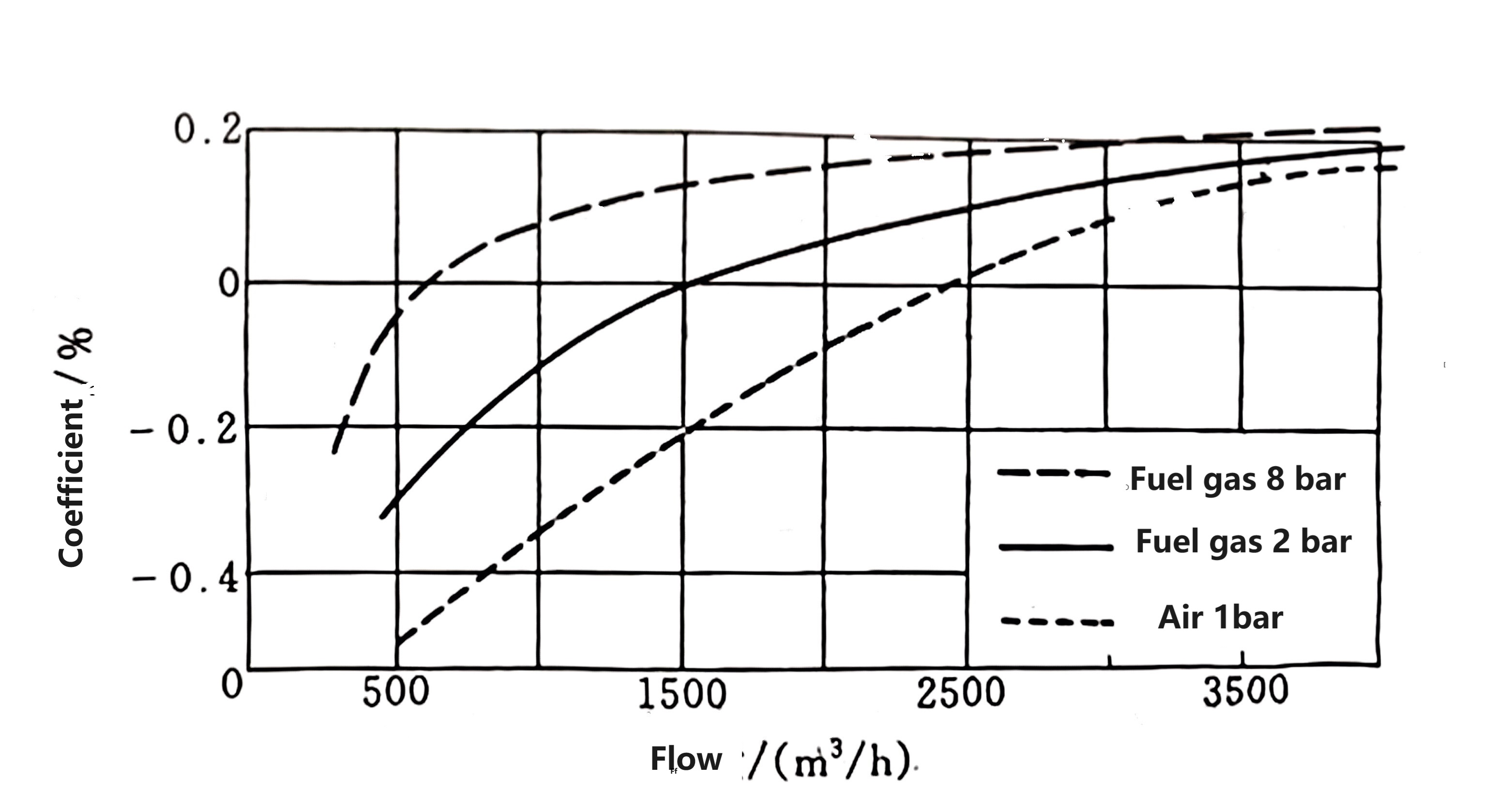
Gas pressure and factor error relation
Turbine flow meter measures the actual
volume flow. Whether it is material balance or energy measurement, it is
necessary to measure the mass flow (i.e. standard flow). The volume flow rate
under this condition) should be converted by the following formula:
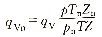
In the formula
qv,qvn – volume flow under operation pressure and standard pressure , m3/h
P,T,Z-Under operation condition absolute pressure(Pa), thermodynamic temperature (K) and gas compressibility coefficient
Pn,Tn,Zn- are respectively the absolute pressure (Pa), thermodynamic temperature (K) and gas compressibility coefficient under standard conditions.


As one of the main flowmeters for trade settlement in energy measurement, turbine flow meter attaches great importance to the formulation of legal documents all over the world, because it is an important basis for regulating the relationship between supply and demand. The International Organization for Standardization (ISO) promulgates international standards ISO 2715, ISO 9951, and the International Organization of Legal Metrology (OIML) promulgates international recommendations R6, R32.
ISO 2715 is the specification for liquid TUF measurement of liquid hydrocarbons. It stipulates the selection of flow meters and auxiliary equipment, flow conditions, pipeline installation and electrical connections, as well as flow meter performance, use and maintenance.
ISO 9951 is the international TUF standard for gas, which specifies the instrument structure, pressure test, flowmeter characteristics, reading device, field calibration, pressure loss, pipe section installation requirements, etc. In particular, to meet the needs of field installation, the flowmeter is required to be installed without a long straight pipe section under severe flow disturbance, which places extremely high requirements on the performance of the flowmeter product, which is relatively rare among flowmeters.
OIML R6, R32 are international recommendations for gas TUF. From the perspective of measuring instruments, in addition to general flow meter structure and performance regulations, they also make clear provisions for type approval, initial calibration, and subsequent calibration.
The standards of developed industrial countries such as API 2534, AGA NO7, JIS Z8765, JIS B7501, etc. on TUF are summaries of many years of practical use. They are very practical and widely recognized internationally.
China also attaches great importance to the formulation of TUF standards and regulations. As early as the 1980s, the TUF industry standard was promulgated. The standard stipulates terminology, classification, technical requirements, test methods and inspection rules, and introduces installation requirements, the influence of fluid temperature, pressure and viscosity changes on instrument coefficients in the appendix. The standard was revised in 1999. China promulgated the verification regulations in the early 1980s, and it has been revised several times. In addition, TUF, as the standard meter of the standard meter method flow standard device, has formulated a special verification regulation.
 Liquid Turbine Flow Meter2017/04/12Liquid Turbine flow meter is a kind of low cost digital flow meter for diesel ,petrol,water,palm oil. it is for clean, low viscosity ,non-corrosive liquid.VIEW
 Gas Turbine Flow Meter2017/04/12Robust Gas flow meter for natural gas,LPG,biogas flow measurement.Inquiry Gas TUF Flowmeter price with EVC directly from China manufacture.VIEW
 Sanitary Hygienic Liquid Turbine Flow meter2018/11/21Hygienic Turbine Flow meter is for clean water, milk, palm oil, edible oil, vegetable oil, fish oil flow measurement ,it is used in the dairy, beverage, food processing and pharmaceutical industries.VIEW
 Low Flow Liquid Turbine Flow meter2018/11/22Mini-flowmeter to measure Low flow rate from 0.035 L/min to 3 L/min for clean and non-corrosive liquids flow measurement.VIEW
 SLW-N Liquid Turbine flow sensor2019/06/01Low cost turbine flow sensor.
 Battery operated liquid turbine flow meter2019/05/273.6V lithium battery operated.
 Wafer liquid turbine flow meter2019/08/07Wafer process connection.
 In-line large size gas turbine flow meter2019/07/30DN350 (14 inches) \DN400 (16 inches) large size gas turbine flow meters can measure the flow of gas or air in closed pipeline. It can measure low pressure or high pressure gas. It is widely used for t...VIEW
 Natural gas turbine flow meter2019/08/14Turbine flow meter for natural gas.