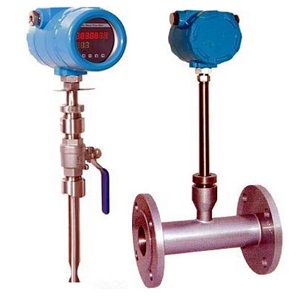
Thermal Mass Flow meter is used to measure gas, such as air , compressed air , biggas,LPG and so on , This article is mainly talking about the installation inforamtion about thermal mass flow meter.

Below we list some cases for straight pipe lines:

Mass Flow meter Installation Pictures
|
No. |
A-Upstream straight Length needed |
B-DownStream Straight length needed |
|
1 |
15D |
5D |
|
2 |
20D |
5D |
|
3 |
40D |
10D |
|
4 |
15D |
5D |
|
5 |
30D |
10D |
|
6 |
40D |
5D |
If the pipelines straight length cannot be met due to field limitation, end users can consider gas rectifiers to solve the problem.
When there are not long enough straight length pipes, and there are bents or valves on the pipe lines, please ask thermal mass flow meter manufacture for installation advice.
1. Thermal flow meter probe inserting depth needed
The air is passing in the pipelines; air velocity is different in different points of the pipe. The gas flow rate near the pipe wall is slower than that in the center of the pipe. Thermal mass flow meter actually detecting the gas velocity sensor; the flow is equal to the sectional area of the pipe multiply the flow rate.
Q=SV
S1=πR2
S2=ab
S=section area of the pipe
R=Radius of the round pipe
a,b=side length of square pipe
V=gas flow velocity
Q=mass flow
Thermal mass flow meter is measuring one point gas velocity of the pipeline; this point should be the average velocity point when applying the above formula. The sensor should be inserted to the average velocity point when installation.
2. According to the design standard, SRK-100 thermal mass flow meter should install as following:
When there is long enough straight pipes or the pipe diameter is>Ø250,the sensor should be in the¼ of the pipeline.
When the straight pipe is short or the pipe diameter≤Ø250, the sensor should be in the ½ of the pipeline.
3. Insertion type and take out
1) Open a Ø20 hole on the pipeline, weld a nipple base, the nipple will be provided by the manufacture.
2) Ball valve will be provided by the manufacture to avoid gas leaking.
1. In most cases, twisted pair cable can be used to supply power.
2.Sheild cable can also be used, for example 3×33/0.2 or RVVP.Core wire should be over Ø0.5.
3. The cable should be lower than instruments when connecting the cable to instruments to avoid water flowing into the flow meter.
4. For Ex-flow meter, Ex-flexible pipes should be used; the OD of the cable should match the ID of cable glands. Sealing gasket should be provided by the factory.
1) The housing cannot connect to the internal circuit, but wiring.
2) The power supply can be switching power supply.
|
|
|
Compact Thermal Mass Flow meter Wiring |
|
|
|
Remote Type Thermal Mass Flow meter Wiring |
|
Red-Red |
Power supply+ |
|
Black-Black |
Power supply- & meter 4-20mA outputnegative(-) |
|
White-White |
meter 4-20mA output positive(+) |
The remote type thermal mass flow meter is 3 wire system, two of them is for power supply , one for signal output.