
Each cycle of the moving element displaces
a volume ![]() . If the
moving component completes
. If the
moving component completes ![]() cycles , the total volume of fuel
cycles , the total volume of fuel ![]() that has passed through the flowmeter is calculated by:
that has passed through the flowmeter is calculated by:![]()
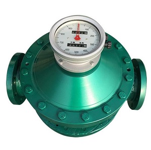
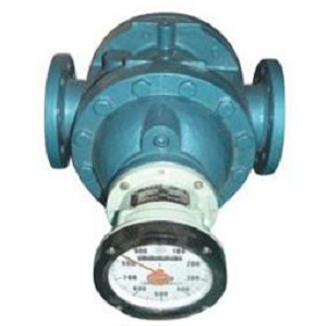
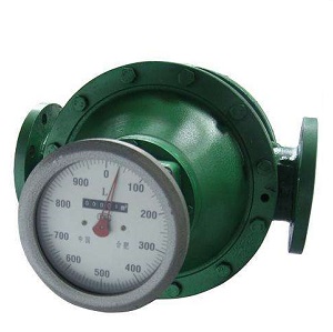
The mechanical movement of the component is
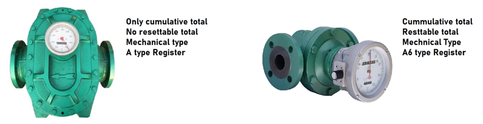
transmitted through a gear mechanism to an indicator, which then moves the
pointer on a dial. This dial displays the total volume of fuel that has passed
through the flowmeter.
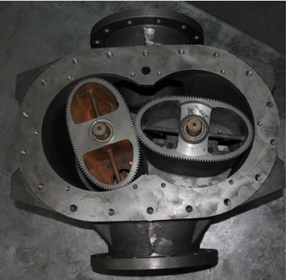
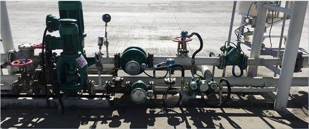
Oval gear flow meter is a kind of positive
displacement flowmeter which is a widely used mechanical fuel flowmeter that measures fuel oil flow by repeatedly capturing a fixed volume. Known for its
one-directional flow, it is referred to as a "positive displacement
flowmeter" in various regions.
It boasts a long history and broad
applicability, with notable advantages:
1. High Measurement Accuracy: Achieves a
relative error of ±0.1% to ±0.5%. oval gear flow meter accuracy remains
unaffected by fuel oil type, viscosity, density, Reynolds number, or the length
of the upstream and downstream straight pipe sections.
2. Wide Measurement Range: Oval gear flow
meter is capable of achieving an accuracy of 0.5 at a range of 10. It provides
precise cumulative fuel oil measurements, making it suitable for material
measurement applications.
3. Effective at Low Reynolds Numbers:
Measures high-viscosity and low-flow-rate fuel with high precision, even in low
Reynolds number conditions, can be used as high viscosity fuel flow meter.
4. Short Straight Pipe Section when install
mechanical fuel flow emter: Functions effectively on-site with minimal
requirements for upstream and downstream straight pipe sections.
Disadvantages of mechancial fuel flow meter
However, there are several disadvantages
associated with positive displacement type fuel flowmeters that must be
considered:
1. Bulk and Complexity: For the same flow
capacity, positive displacement flowmeters tend to be bulkier due to their
larger volume and the greater number of mechanical components. The assembly
process is more complex, leading to higher manufacturing costs.
2. Sensitivity to Contaminants: These fuel
flowmeters are generally sensitive to particulates and contaminants in the fuel.
Installing a filter upstream can increase pressure loss. Additionally,
components such as the rotor and housing require periodic cleaning, which adds
to maintenance efforts.
3. Susceptibility to Flow Rate Variations:
Frequent changes in flow rate can damage the rotating parts. It is crucial to
avoid sudden opening or closing of valves near the diesel flowmeter, as such
actions can lead to instrument damage if not properly managed by the operator.
Despite these limitations, positive displacement flowmeters remain a widely used and reliable fuel flow metering instrument due to their high accuracy and long service life. They are commonly employed in industries such as oil measurement and trading, light manufacturing, food processing, and other sectors.
To conduct a precise error analysis of
mechanical fuel flow meters, one must consider several critical factors.
Assuming the machining precision and assembly standards are upheld, the primary
sources of systematic error include leakage or slippage, which arises due to
the clearance between the measuring element (such as a rotor, scraper, or
piston) and the internal cavity of the housing. Another significant factor is
the change in the volume of the metering chamber, which can occur due to
deformation of the housing caused by fluid pressure, mechanical stress, and
temperature fluctuations.
Leakage is influenced by the gap size,
fluid viscosity, and the pressure differential between the flowmeter's inlet
and outlet (which is related to the movement resistance of the measuring
element, the transmission mechanism, and the fluid's flow resistance within the
housing). While minimizing the gap can reduce leakage, it also increases
manufacturing complexity and risks jamming the moving components, or at the
very least, elevating resistance. Thus, the gap cannot be minimized
indefinitely. The rotor's resistance to rotation, which is overcome by the
pressure differential between the inlet and outlet, coupled with the pressure
loss caused by fluid viscosity within the metering chamber, contributes to the
overall pressure differential that drives fluid leakage through the gap.
Factors such as increasing the gap, decreasing viscosity, increasing pressure
differential, increasing density, and heightened rotational resistance all
exacerbate leakage. For high-precision volumetric flow meters, minimizing leakage
is essential, requiring the rotor to rotate freely with minimal resistance
torque, ensuring a small pressure differential, maintaining an appropriately
small gap, and selecting a fluid with moderate viscosity.
When selecting volumetric flowmeters, particularly for applications like fuel oil product measurement, trade, and
material accounting, careful consideration must be given to ensure optimal
performance and accuracy. The following guidelines should be observed:
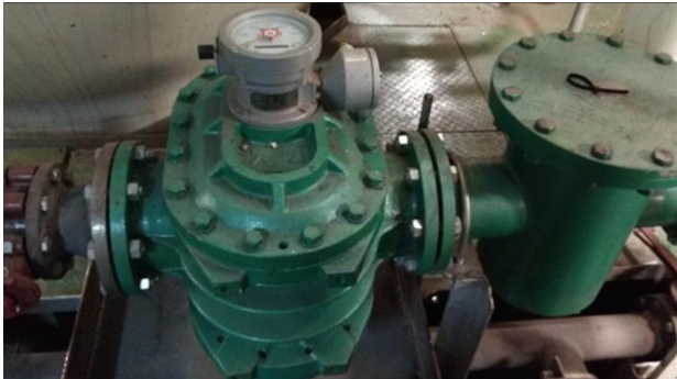
When installing and maintaining volumetric
type fuel oil flow meters, particularly for applications involving precise
measurements such as trade or standard delivery, adherence to the following
guidelines is essential to ensure accurate performance and longevity:
1. Install Site Selection: The
installation site should conform to the fuel flow meter's operational
guidelines, ideally being indoors. If outdoor installation is necessary, a
protective enclosure should be used to mitigate the effects of environmental
exposure. For sites with explosion-proof requirements, select a flow meter that
meets the necessary explosion-proof ratings.
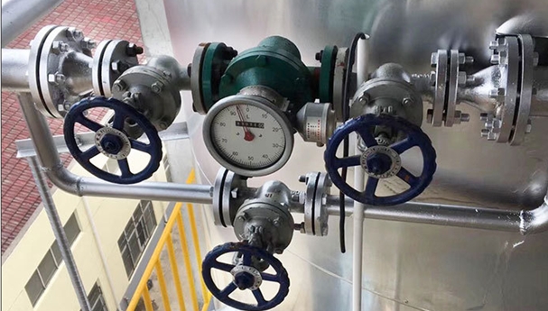
2. Installation Precautions: Ensure that
the flow direction indicated on the fuel flow meter aligns with the actual
fluid flow, such as gasoline, diesel. If needed, install a check valve to
prevent reverse flow, except in cases where a bidirectional flow meter is
specifically designed for such purposes. Before installation, the upstream
piping must be thoroughly cleaned, followed by the installation of a filter and
the flow meter. In certain cases, an air eliminator may be required. The valve
used to regulate the diesel flow should be positioned downstream of the flow
meter to maintain a fully filled pipeline during operation. When connecting the
flow meter to the pipeline, avoid applying mechanical stress to the meter's
housing that could cause deformation. The pipeline should be securely supported
to prevent movement, and sufficient clearance should be provided around the flow
meter for maintenance access.
3. Pre-Installation Testing: For fuel flow
meters used in trade or precision measurement applications, metrological
performance should be verified before installation. The diesel flow meter
should only be installed after confirming its accuracy and ensuring operation
within the optimal flow range, as indicated in the calibration certificate.
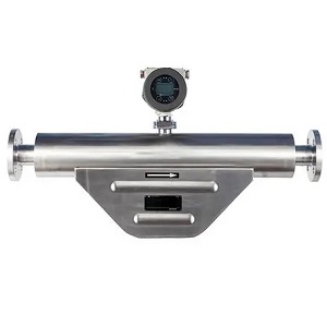 Fuel Oil Mass Flow Meter
2024/09/16
A fuel oil mass flow meter is a type of flow meter that is specifically designed to measure the mass flow rate of fuel oil in a pipeline or process system. Coriolis flow meter is a kind of accurate fu...
VIEW
Fuel Oil Mass Flow Meter
2024/09/16
A fuel oil mass flow meter is a type of flow meter that is specifically designed to measure the mass flow rate of fuel oil in a pipeline or process system. Coriolis flow meter is a kind of accurate fu...
VIEW
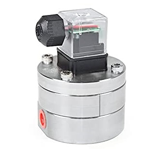 Low flow fuel flow meter
2024/09/16
How low flow fuel flow meter work?Fuels, such as gasoline, diesel fuel, bio-diesel, kerosene, and ethanol may run at low flow rate. Such as at ml/min or lph velocity, in that condition, ultra low flow...
VIEW
Low flow fuel flow meter
2024/09/16
How low flow fuel flow meter work?Fuels, such as gasoline, diesel fuel, bio-diesel, kerosene, and ethanol may run at low flow rate. Such as at ml/min or lph velocity, in that condition, ultra low flow...
VIEW
 Positive displacement flow meter for fuels and oils
2024/09/16
Why positive displacement flow meters can be used for fuels and oils?Fuels or oils volumetric flow measurement refers to diesel, petroleum based fuels, kerosene, home heating oil, jet fuel, diesel fue...
VIEW
Positive displacement flow meter for fuels and oils
2024/09/16
Why positive displacement flow meters can be used for fuels and oils?Fuels or oils volumetric flow measurement refers to diesel, petroleum based fuels, kerosene, home heating oil, jet fuel, diesel fue...
VIEW
 Positive displacement flow meter
2024/09/16
Positivedisplacement flow meterA positive displacement flow meter is adevice that helps in measuring the flow rate of various fluids. It measures thevolumetric flow rates of the fluids. These meters a...
VIEW
Positive displacement flow meter
2024/09/16
Positivedisplacement flow meterA positive displacement flow meter is adevice that helps in measuring the flow rate of various fluids. It measures thevolumetric flow rates of the fluids. These meters a...
VIEW
 Mechanical register oval gear flow meter
2024/09/16
Mechanical counter oval gear flow meter is a kind of in-line positive displacement flow meter where main power is impossible in the field or the field only request basic metering, no output transmissi...
VIEW
Mechanical register oval gear flow meter
2024/09/16
Mechanical counter oval gear flow meter is a kind of in-line positive displacement flow meter where main power is impossible in the field or the field only request basic metering, no output transmissi...
VIEW
 The Complete Manual for Diesel Flow Meters: Coriolis, Oval Gear, and Turbine
2024/09/16
Diesel fuel powers everything from heavy machinery and transportation to industrial boilers and backup generators, making it a vital component of the global economy. Accurately measuring diesel flow a...
VIEW
The Complete Manual for Diesel Flow Meters: Coriolis, Oval Gear, and Turbine
2024/09/16
Diesel fuel powers everything from heavy machinery and transportation to industrial boilers and backup generators, making it a vital component of the global economy. Accurately measuring diesel flow a...
VIEW


 Email
Email
 WA
WA
 Inquiry


