
Related Products

Oval Gear Flow meter is for diesel, crude oil, resin, fuel, heavy oil flow measurement. PD flow meter is with mechanical register or digital display, Inquiry Price now.
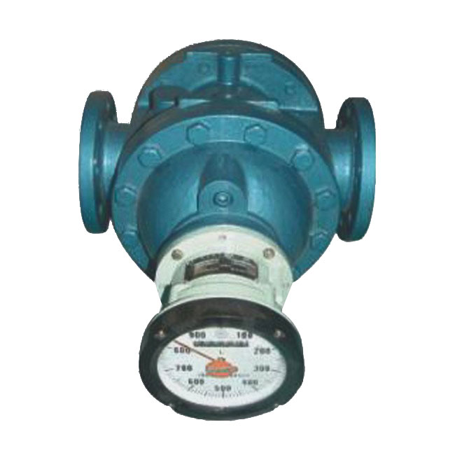
Positive displacement flow meter
A couple of helical gear
Low noise and No pulsation
High accuracy
For crude oil, fuel or high viscosity liquid
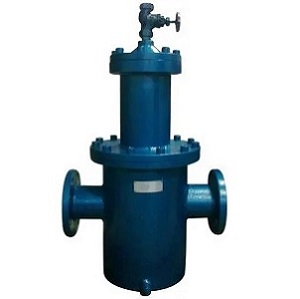
The LPG-X type Air eliminator and strainer,
as auxiliary equipment for flow metering, is mainly used to filter the
particulate impurities contained in the measured liquid, and can separate and
exclude gases from it. In most cases, the measured liquid will contain various
impurities and gases to varying degrees. These impurities and gases entering
the flow meter will affect the metering accuracy of it. Therefore, in flow
metering systems, especially high-precision flow metering systems, degassing
filters are indispensable auxiliary equipment.
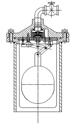
The Air eliminator and strainer is composed of several main parts, such as the housing, degassing valve, and filter screen. The housing should withstand the working pressure of the measured liquid and form a space that meets the requirements for filtration and degassing. The degassing valve controls the switch of the main and auxiliary valves through the upward, as well as downward movement of the floating ball to achieve the purpose of exhaust.
When the liquid enters the degassing filter, it first impacts the baffle plate to disperse the liquid flow. The liquid and gas rises along the baffle plate to the top of the housing, forming a gas phase space. With the continuous expansion of the gas phase space, the liquid interface continues to decline, and the floating ball drops under the effect of its own weight, driving the valve stem to move, so that the auxiliary valve opens first to exhaust some gas. If the gas volume is greater than the gas discharged by the auxiliary valve, the floating ball will continue to drop, driving the valve stem to open the main valve and expel a large amount of gas. At this point, the liquid gas interface gradually rises. First, close the auxiliary valve, and the floating ball gradually rises to close the main valve. This repeatedly achieves the purpose of exhaust. The liquid separated by liquid and gas enters the filter screen, and the filtered liquid enters the flow meter.
|
Nominal diameter mm |
Mesh number |
Nominal pressure MPa |
Medium temperature ℃ |
Medium density kg/m3 |
Medium viscosity mPa.s |
Pressure loss MPa |
|
40 |
60 |
1.0 1.6 2.5 |
-20~120 |
≥0.80×10³ |
2~500 |
≤0.07 |
|
50 |
60 |
|||||
|
80 |
40 |
|||||
|
100 |
40 |
|||||
|
150 |
40 |
|||||
|
200 |
40 |
|||||
|
250 |
20 |
|||||
|
300 |
20 |
|||||
|
350 |
20 |
|||||
|
400 |
20 |
|||||
|
450 |
10 |
|||||
|
500 |
10 |
|||||
|
550 |
10 |
Note: Special mesh number can be determined according to user needs.
|
Mark |
Code |
Description |
|
Product Code |
LPG-X |
LPG-X Type Degassing Filter |
|
Material |
B C E |
Stainless steel 304 Stainless steel 316 Cast steel |
|
Diameter |
40~400mm |
Size from 40mm to 400mm |
|
Pressure rating |
1 2 3 |
1.0Mpa 1.6Mpa 2.5Mpa |
|
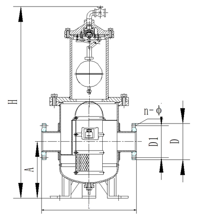
Material |
Nominal diameter |
Connection length L |
Installation height A |
Total height H |
D |
D1 |
n-φ |
|
|
Pressure |
GB/T9112-2010 |
|||||||
|
Welding |
50 |
300 |
155 |
700 |
1.6 |
φ165 |
φ125 |
4-φ18 |
|
2.5 |
φ165 |
φ125 |
4-φ18 |
|||||
|
80 |
400 |
250 |
860 |
1.6 |
φ200 |
φ160 |
8-φ18 |
|
|
2.5 |
φ200 |
φ160 |
8-φ18 |
|||||
|
100 |
500 |
280 |
970 |
1.6 |
φ220 |
φ180 |
8-φ18 |
|
|
2.5 |
φ235 |
φ190 |
8-φ23 |
|||||
|
150 |
600 |
335 |
1150 |
1.6 |
φ285 |
φ240 |
8-φ22 |
|
|
2.5 |
φ300
|
φ250 |
8-φ26 |
|||||
|
200 |
786 |
395 |
1750 |
1.6 |
φ340 |
φ295 |
12-φ23 |
|
|
2.5 |
φ360 |
φ310 |
12-φ26 |
|||||
|
250 |
950 |
650 |
2000 |
1.6 |
φ405 |
φ355 |
12-φ26 |
|
|
2.5 |
φ425 |
φ370 |
12-φ30 |
|||||
|
300 |
950 |
700 |
2100 |
1.6 |
φ460 |
φ410 |
12-φ26 |
|
|
2.5 |
φ485 |
φ430 |
16-φ30 |
|||||
|
350 |
1200 |
750 |
2250 |
1.6 |
φ520 |
φ470 |
16-φ26 |
|
|
2.5 |
φ555 |
φ490 |
16-φ34 |
|||||
|
400 |
1200 |
750 |
2360 |
1.6 |
φ580 |
φ525 |
16-φ30 |
|
|
2.5 |
φ620 |
φ550 |
16-φ34 |
|||||
Note: The import and export flange standards can also be manufactured according to relevant standards according to user needs

we will contact you within 24 hours.


 English
  français
  Español
  русский
  português
  العربية
  tiếng việt
  Türkçe
  ไทย
ไทย  українська
  Malay
Malay  עברי
עברי  Indonesia
  Ελλάδα
  ಕನ್ನಡ
ಕನ್ನಡ  հայերեն
 Email
Email
 WA
WA
 Inquiry


