Pressure transmitters are generally
available in various forms except for special designs and models, which are designed
for specific applications. Options differ in regard to their pressure range,
electrical and pressure connection, output signal, and measurement accuracy.
With so many possible configurations, the selection of a suitable pressure transducer
measurement instruments for a specific application can be a complex process.
This overview presents the most important specifications for pressure
measurement instrument selection.
Pressure Range
The first option that should be considered
is the pressure sensor range of the pressure measurement instrument. The
pressure range defines the limits of how much pressure can be measured or
monitored in an application. Essential to the pressure range specification are
the lower and upper limits of the pressure range, and if the range is absolute
pressure or gauge pressure. The accuracy data specified in the data sheet
applies within the defined pressure range.
Pressure Connection
The second option that should be considered
is the pressure connection, also referred to as the process connection. The
pressure connection is used to direct the pressure medium to the pressure sensor.
Almost all pressure connections have a standard thread and can be installed at
the pressure measurement point.
Internal vs. Flush Diaphragms
Another option to consider is internal
diaphragms versus flush diaphragms. There is a difference between pressure
connections with an internal diaphragm and connections with a flush (flat)
non-clogging diaphragm. In process connections with an internal diaphragm the
pressure medium directly contacts the pressure sensor diaphragm through the
pressure port. In process connections with a flush diaphragm, the pressure port
is sealed using an additional stainless-steel diaphragm. A transmission fluid
transmits the pressure from the flat external diaphragm to the internal sensor
diaphragm.
Threads & Seals
Threads and seals provide a multitude of
options. To enable the simultaneous installation and sealing of the measurement
instrument at the measurement point, the pressure connections are usually designed
with a thread. Different threads are commonly used worldwide and both male and
female threads are available. Sealing methods are as diverse as the threads.
Some threads including tapered threads are self-sealing. Other threads require
an additional seal, gasket, or o-ring. For this there are different
application-specific and regional solutions. The most common for parallel
threads are sealing behind the thread (i.e. between the thread and the case) or
sealing in front of the thread by means of a metal sealing ring.
Electrical Connection
The electrical connection of an electronic
pressure transmitter measurement instrument also presents multiple options, a
standard plug-in connector or an integral cable. The nature of the connection
has considerable influence on the IP (Ingress Protection) rating of the
instrument and often limits the permissible ambient temperature range, and the
resistance of the instrument to aggressive media, or environmental influences
(e.g. UV radiation).
Output Signals of pressure transmitter
Output signals of electronic pressure
transmitter measurement instruments are generally an analog voltage or current
signal, which is transmitted to a control unit connected downstream of the
instrument. However, pressure measurement instruments are also available with
digital outputs. With the exception of switching output signals, which are
already in a digital format, the output signal should be linear and
proportional to the applied pressure.
Standard Analog Output Signal
Other output signals include standard
analog output, ratiometric output, and digital output. The most common output
signal in pressure measurement technology is the analog output signal. Commonly
used are the current signal 4-20 mA and the voltage signals 0-5 V, 0-10 V and
1-5 V. In comparison to voltage signals, the advantages of the current signals
are a much lower sensitivity to electromagnetic interference and automatic
compensation of resistive loads the current loop. The elevated zero point of
the 4-20 mA current signal and likewise with the 1-5 V voltage signal also
provides cable break detection separately from instrument fault


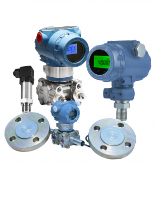 Pressure Transmitters2017/04/12Pressure Transmitter
 Capacitance Pressure Transmitter2017/04/26Digital Capacitive Pressure Transducer.
 Pressure and DP Transmitter with Flange Diaphragm2017/04/12Flange diaphragm Transmitter.
 Pressure Transmitter with Remote Diaphragm seals2017/04/12Remote diaphragm for corrosive or viscous fluids.
 Pressure Sensor2017/04/12Low cost Pressure sensor.
 SH 308 Series Pressure Transmitter2017/04/26Piezoresistive pressure cost is low;


